S-R Latch using Truth Table. Assume that the Flip-flop is in Set state, means Q = 0, then Q’ should be 1 because it is complement of Q. Let’s see what happens in the NOR implementation of S-R latch. R = 0 and S = 0. Digital Electronics: Truth Table, Characteristic Table and Excitation Table for SR Flip FlopContribute: http://ww.
In the last experiment, the logic circuits introduced were combinational. These circuits do not have memory cells and their output depends only upon the current value of the input. Memory cells are very important in digital systems. Their usage in digital circuits provides temporary storage of the outputs produced by a combinational logic circuit for use at a later time in the operation of a digital system.
Logic circuits that incorporate memory cells are called sequential logic circuits; their output depends not only upon the present value of the input but also upon the previous values. Sequential logic circuits often require a timing generator (a clock) for their operation.
The latch (flip-flop) is a basic bi-stable memory element widely used in sequential logic circuits. Usually there are two outputs, Q and its complementary value. They are called state variables. State variables which change only between logic 1 and logic 0 are called binary state variables. There are various types of latches. Some of the most widely used latches are listed below.
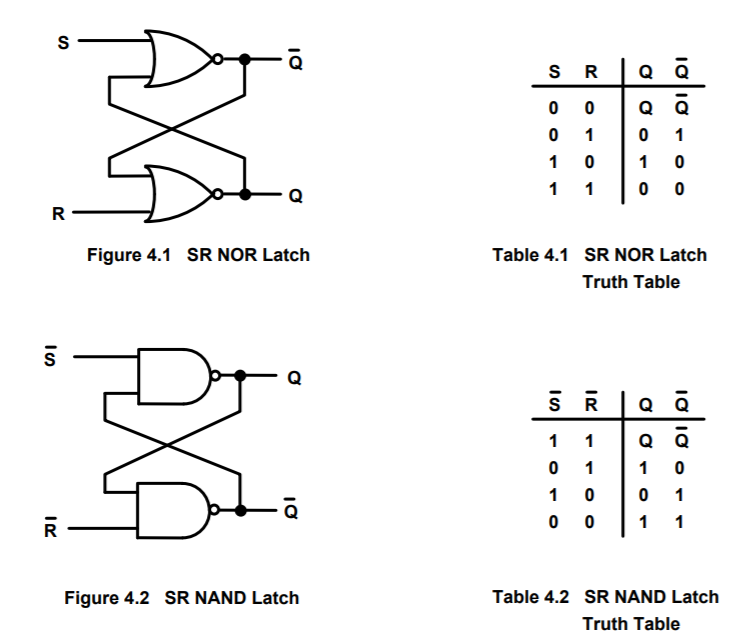
S-R FIip-Flop:An S-R latch consists of two cross-coupled NOR gates and possibly two inverters, as shown in Fig. 1. An S-R flip-flop can also be design using cross-coupled NAND gates as shown in Fig. 2. Table 1 shows the truth tables for both cases. Note that a negative logic signal such as R is considered asserted (logical 1) when low.
| Table 1. Truth table for S-R latch | ||||||||
|---|---|---|---|---|---|---|---|---|
| S-R Latch NOR gates | S-R Latch NAND gate | |||||||
| R | S | Q | Q | R | S | Q | Q | |
| L | L | NC | NC | L | L | H | H | |
| L | H | H | L | L | H | L | H | |
| H | L | L | H | H | L | H | L | |
| H | H | L | L | H | H | NC | NC | |
| NC- no change | ||||||||
Clocked (Enabled) S-R Flip-Flop:

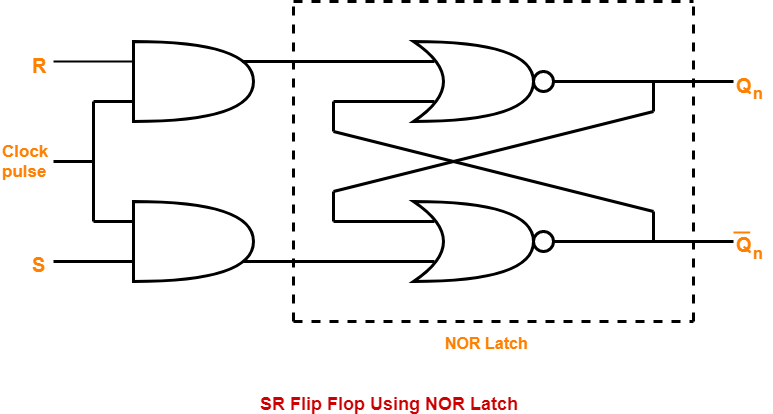
As shown in Fig. 3, a clocked S-R flip-flop has an additional clock input so that the S and R inputs are active only when the clock is high. When the clock goes low, the state of flip-flop is latched and cannot change until the clock goes high again. Therefore, the clocked S-R flip-flop is also called “enabled” S-R flip-flop.
D Flip-Flop:
A D latch combines the S and R inputs of an S-R latch into one input by adding an inverter, as indicated in Fig. 4. When the clock is high, the output follows the D input, and when the clock goes low, the state is latched.
D Edge-Triggered Flip-Flop:
An edge-triggered D flip-flop combines two D latches, as shown in Fig. 5. The input latch is called the master and follows the input while the clock is low. When the clock goes high, the master is latched and its output is transferred to the second latch, called the slave. The slave output is seen by the user. Hence the edge-triggered D flip-flop senses the input data present at the rising edge of the clock and provides a corresponding output. The output can only change at the rising clock edge. The small triangle on the “CLK” terminal on the symbol represents its edge-triggering.
J-K Master/Slave Flip-Flop:
As shown in Fig. 6, a J-K master/slave flip-flop is similar to an edge-triggered D flip-flop except that J and K inputs are provided for the master. Although the output can change only at the rising clock edge, a J-K master/slave flip-flop is not truly edge-triggered because the output does not always reflect the inputs present at the triggering edge. Table 2 shows the truth table for the J-K master/slave flip-flop.
| Table 2. Truth table for J-K flip-flop | ||||
|---|---|---|---|---|
| J | K | Q | Operation | |
| L | L | q | No Change | |
| L | H | L | Reset | |
| H | L | H | Set | |
| H | H | q | Toggle | |
J-K Edge-Triggered Flip-Flop:
Fig. 7 shows one way of implementing a true J-K edge-triggered flip-flop, which produces an output that depends only upon the input data present at the rising edge of the clock. Unlike combinational logic circuits, sequential logic circuits present some special issues.
Race Condition:

A race condition can occur when two values are supposed to change simultaneously, but one may actually be quicker than the other. Consider a simple 2-bit counter that goes through the sequence 00, 01, 10, 11, 00, … When the value is 01, we want the counter to change to 10 next. The most significant bit would change from 0 to 1 and the least significant bit would change from 1 to 0. But what happens if the most significant bit changes faster than the least significant bit? In this case, the sequence would go from 00 to 01 and then to 00. If the difference in time is sufficiently large, the counter might just loop between 00 and 01 forever, never reaching 10 and 11.
Gated Sr Latch Truth Table
If both inputs to the S-R flip-flop in Fig. 1 are changed from logic 1 to logic 0 at the same time, its outputs will be unpredictable and we call that a race condition. In logic circuit design, this condition should be avoided by making sure that 1's are not applied to both inputs simultaneously.
Set-up Time:
Sr Flip Flop
Set-up time for flip-flops is defined as the time interval during which a signal must be applied and maintained at a specific input terminal before an active transition occurs at the clock input. For example, set-up time for a D flip-flop is defined as the time required for the data to be present (above, or below, a threshold value) on the input before the clock transition (edge) occurs.